

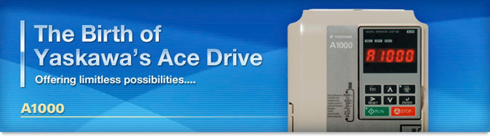
Yaskawa A1000
| A1000 Drive 3/4 – 1000 HP | |||||||||||
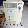
| The A1000 is a full featured drive, providing outstanding quality, performance, flexibility, and environmental friendliness through 1000HP. Enjoy network communications, feedback, and expandable I/O to control anything from simple fans and pumps to complex machines. For new installations or retrofits, the A1000 provides a single robust solution, regardless of your application. | |||||||||||
| A1000 Drive Features Highlights: | |||||||||||
|
Closed or open loop vector control for outstanding regulation, torque production, and position control capability. |
|||||||||||
| Continuous Auto-tuning optimizes performance by compensating for changes in motor temperature. | |||||||||||
| High Frequency Injection enables high precision open loop control of Interior Permanent Magnet Motors. | |||||||||||
| Fast acting current and voltage limiters help achieve continuous drive operation during periods of excessive demand. | |||||||||||
| High Slip Braking reduces installation cost and the need for dynamic braking resistors | |||||||||||
| Communication options for all major industrial networks provides high speed control and monitoring, reducing installation cost. | |||||||||||
| DriveWizard computer software and Application Sets for easy configuration. | |||||||||||
| Auxiliary Control Power Unit maximizes production time and efficiency by maintaining network communication while main power is removed. | |||||||||||
| Embedded Safe Torque Off minimizes downtime for applications requiring occasional intervention (SIL CL2, PLd, Category 3). | |||||||||||
| Embedded function blocks, programmable with DriveWorks EZ, provide additional application flexibility and the opportunity to eliminate separate controllers. | |||||||||||
| USB Copy Unit and Keypad configuration storage provide speed and convenience for duplicate configuration of multiple drives. | |||||||||||
| Removable terminal board with configuration storage provides convenience of configuration backup. | |||||||||||
| Made with RoHS compliant materials. | |||||||||||
| Integrated DC Reactor (standard on 30HP and larger) for input harmonic reduction. | |||||||||||
| Kinetic Energy Braking allows drive to remain in control during momentary power losses. | |||||||||||
| Integrated 12 Pulse version provides a cost effective solution for low harmonics. | |||||||||||
| Flange version provides NEMA 12 backside integrity when mounting with heatsink external. | |||||||||||
| A1000 Drive Specifications | |||||||||||
|
ITEM |
SPECIFICATION |
||||||||||
| Overload Capacity | 150% for 60 sec. (HD), 120% for 60 sec. (ND) | ||||||||||
| Output Frequency | 0~400 Hz (higher frequencies available with custom software) | ||||||||||
| Control Methods | Open and Closed Loop Current Vector; | ||||||||||
| Open and Closed Loop V/f | |||||||||||
| Motor Types | Induction | ||||||||||
| Surface Permanent Magnet (excluding 600V class) | |||||||||||
| Interior Permanent Magnet (excluding 600V class) | |||||||||||
| Protective Design | IP20/NEMA1/FLANGE (NEMA 12 backside) | ||||||||||
| Ambient Operating Temperature | -10 to +50°C (Chassis Installation) | ||||||||||
| -10 to +40°C (Chassis with zero side clearance, or Type 1) | |||||||||||
| Braking Transistor | Standard through 50HP (ND), 40HP (HD) | ||||||||||
| Global Certification | UL, CSA, CE, C-Tick, RoHS | ||||||||||
| Standard I/O | (8) multi-function digital inputs (24Vdc) | ||||||||||
| (3) multi-function analog inputs (0 +/- 10 VDC, 4-20 mA) | |||||||||||
| (1) multi-function pulse inputs | |||||||||||
| (1) fault relay output (form C) | |||||||||||
| (3) multi-function relay outputs (form A) | |||||||||||
| (2) multi-function analog output (0 +/- 10 VDC, 4-20mA) | |||||||||||
| (1) multi-function pulse output | |||||||||||
| I/O Expansion | 3 Analog Inputs -10 to +10V, 13 bit plus sign, 4 to 20mA | ||||||||||
| 16 Digital Inputs (+24V for BCD speed reference) | |||||||||||
| 2 Analog Outputs (-10 to +10V, 11 bit magnitude) | |||||||||||
| 8 Digital Outputs (6 transistor, 2 relay) | |||||||||||
| Feedback | Incremental | ||||||||||
| Absolute (Stegmann, Heidenhain EnDat, Resolver) | |||||||||||
| Resolver | |||||||||||
| Network Communication | Built-in: | ||||||||||
| Modbus RTU, RS-422/485, 115 kbpsOptional: | |||||||||||
| EtherNet IP, DeviceNet, Modbus TCP/IP, PROFINET, PROFIBUS-DP, MECHATROLINK-II | |||||||||||
| Speed Control Range | 1500:1 Closed Loop Vector (IM and PM Motors) | ||||||||||
| 200:1 Open Loop Vector (IM Motors) | |||||||||||
| 100:1 Open Loop Vector (PM Motors) | |||||||||||
| Speed Control Accuracy | £ 0.02%: Closed Loop Vector; ≤ 0.2%; Open Loop Vector | ||||||||||
| Speed Response | ≥ 60 Hz: Closed Loop Vector; ≥ 10 Hz: Open Loop Vector | ||||||||||
| Torque Response | ≥ 300 Hz: Closed Loop Vector | ||||||||||
| Function Block Diagrams | Up to 100 connections, 1ms program scan time | ||||||||||
| A1000 Drive Models & Ratings | |||||||||||
|
A1000 Drive 200-240V, 3-Phase, Protected Chassis/NEMA 1 |
|||||||||||
|
DRIVE MODEL |
NORMAL DUTY (ND) |
HEAVY DUTY (HD) |
ENCLOSURE |
||||||||
|
CURRENT |
NOMINAL HP |
CURRENT |
NOMINAL HP |
||||||||
|
CIMR-AU2A0004FAA |
3.5 |
4-Mar |
3.2 |
4-Mar |
NEMA 1 |
||||||
|
CIMR-AU2A0006FAA |
6 |
1 |
5 |
1 |
|||||||
|
CIMR-AU2A0008FAA |
8 |
2 |
6.9 |
2 |
|||||||
|
CIMR-AU2A0010FAA |
9.6 |
2 |
8 |
2 |
NEMA 1 |
||||||
|
CIMR-AU2A0012FAA |
12 |
3 |
11 |
3 |
|||||||
|
CIMR-AU2A0018FAA |
17.5 |
5 |
14 |
3 |
|||||||
|
CIMR-AU2A0021FAA |
21 |
7.5 |
17.5 |
5 |
NEMA 1 |
||||||
|
CIMR-AU2A0030FAA |
30 |
10 |
25 |
7.5 |
|||||||
|
CIMR-AU2A0040FAA |
40 |
15 |
33 |
10 |
|||||||
|
CIMR-AU2A0056FAA |
56 |
20 |
47 |
15 |
NEMA 1 |
||||||
|
CIMR-AU2A0069FAA |
69 |
25 |
60 |
20 |
|||||||
|
CIMR-AU2A0081FAA |
81 |
30 |
75 |
25 |
|||||||
|
CIMR-AU2A0110FAA |
110 |
40 |
85 |
30 |
NEMA 1 |
||||||
|
CIMR-AU2A0138FAA |
138 |
50 |
115 |
40 |
|||||||
|
CIMR-AU2A0169FAA |
169 |
60 |
145 |
50 |
NEMA 1 |
||||||
|
CIMR-AU2A0211FAA |
211 |
75 |
180 |
60 |
|||||||
|
CIMR-AU2A0250AAA |
250 |
100 |
215 |
75 |
Protected Chassis |
||||||
|
CIMR-AU2A0312AAA |
312 |
125 |
283 |
100 |
|||||||
|
CIMR-AU2A0360AAA |
360 |
150 |
346 |
125 |
Protected Chassis |
||||||
| CIMR-AU2A0415AAA | 415 | 175 | 415 | 150 | |||||||
| 1. Normal Duty overload current rating is 120% of rated output current for 60 seconds; Heavy Duty overload current rating is 150% of rated output current for 60 seconds | |||||||||||
| 2. Horsepower rating is based on standard NEMA B 4-pole motor design as represented in NEC table 430.150 Full-Load Current, Three-Phase Alternating Current Motors. Also, listed power ratings assumes three-phase input. For single-phase input applications, consult Manual Supplement TOEPYEASUP03 for proper sizing. | |||||||||||
| A1000 Drive 200-240V, 3-Phase, Flange | |||||||||||
|
DRIVE MODEL |
NORMAL DUTY (ND) |
HEAVY DUTY (HD |
ENCLOSURE1 |
||||||||
|
CURRENT |
NOMINAL HP |
CURRENT |
NOMINAL HP3 |
||||||||
|
CIMR-AU2A0004UAA |
3.5 |
4-Mar |
3.2 |
4-Mar |
Flange |
||||||
|
CIMR-AU2A0006UAA |
6 |
1 |
5 |
1 |
|||||||
|
CIMR-AU2A0008UAA |
8 |
2 |
6.9 |
2 |
|||||||
|
CIMR-AU2A0010UAA |
9.6 |
3 |
8 |
2 |
Flange |
||||||
|
CIMR-AU2A0012UAA |
12 |
3 |
11 |
3 |
|||||||
|
CIMR-AU2A0018UAA |
17.5 |
5 |
14 |
3 |
|||||||
|
CIMR-AU2A0021UAA |
21 |
7.5 |
17.5 |
5 |
Flange |
||||||
|
CIMR-AU2A0030UAA |
30 |
10 |
25 |
7.5 |
|||||||
|
CIMR-AU2A0040UAA |
40 |
15 |
33 |
10 |
|||||||
|
CIMR-AU2A0056UAA |
56 |
20 |
47 |
15 |
Flange |
||||||
|
CIMR-AU2A0069UAA |
69 |
25 |
60 |
20 |
|||||||
|
CIMR-AU2A0081UAA |
81 |
30 |
75 |
25 |
|||||||
|
CIMR-AU2A0110UAA |
110 |
40 |
85 |
30 |
Flange |
||||||
|
CIMR-AU2A0138UAA |
138 |
50 |
115 |
40 |
|||||||
|
CIMR-AU2A0169UAA |
169 |
60 |
145 |
50 |
|||||||
|
CIMR-AU2A0211UAA |
211 |
75 |
180 |
60 |
Flange |
||||||
|
CIMR-AU2A0250UAA |
250 |
100 |
215 |
75 |
|||||||
|
CIMR-AU2A0312UAA |
312 |
125 |
283 |
100 |
|||||||
|
CIMR-AU2A0360UAA |
360 |
150 |
346 |
125 |
Flange |
||||||
|
CIMR-AU2A0415UAA |
415 |
175 |
415 |
150 |
|||||||
| 1. Standard Enclosure can be conventionally mounted, or heatsink external (kit required for models CIMR-AU2A081FAA and smaller). Flange Enclosure includes special factory-installed gasketing and flange to provide NEMA 12 backside integrity when mounting heatsink external. | |||||||||||
| 2. Normal Duty overload current rating is 120% of rated output current for 60 seconds; Heavy Duty overload current rating is 150% of rated output current for 60 seconds | |||||||||||
| 3. Horsepower rating is based on standard NEMA B 4-pole motor design as represented in NEC table 430. 150 Full-Load Current, Three-Phase Alternating Current Motors | |||||||||||
| A1000 Drive 240V, Single-Phase Input, (208-230V Three-Phase Output) | |||||||||||
|
DRIVE MODEL |
SINGLE PHASE INPUT – SIZING METHOD A |
SINGLE PHASE INPUT – SIZING METHOD B |
|||||||||
|
WITHOUT ADDITIONAL REACTOR |
WITH ADDITIONAL REACTOR |
(86% MAX POWER OF CONNECTED MOTOR SIZE) | |||||||||
| MOTOR AMPS | MOTOR SIZE (HP) | MOTOR AMPS | MOTOR SIZE (HP) |
MOTOR AMPS |
MOTOR SIZE (HP) |
||||||
|
CIMR-AU2A0004FAA |
1.7 |
3-Jan |
2.4 |
2-Jan |
2.4 |
2-Jan |
|||||
|
CIMR-AU2A0006FAA |
3.5 |
4-Mar |
3.5 |
4-Mar |
4.6 |
1 |
|||||
|
CIMR-AU2A0008FAA |
4.6 |
1 |
4.6 |
1 |
4.6 |
1 |
|||||
|
CIMR-AU2A0010FAA |
4.6 |
1 |
4.6 |
1 |
6.6 |
1.5 |
|||||
|
CIMR-AU2A0012FAA |
6.6 |
1.5 |
7.5 |
2 |
7.5 |
2 |
|||||
|
CIMR-AU2A0018FAA |
7.5 |
2 |
10.6 |
3 |
10.6 |
3 |
|||||
|
CIMR-AU2A0021FAA |
7.5 |
2 |
10.6 |
3 |
10.6 |
3 |
|||||
|
CIMR-AU2A0030FAA |
10.6 |
3 |
10.6 |
3 |
17 |
5 |
|||||
|
CIMR-AU2A0040FAA |
10.6 |
3 |
17 |
5 |
17 |
5 |
|||||
|
CIMR-AU2A0056FAA |
17 |
5 |
24 |
7.5 |
24 |
7.5 |
|||||
|
CIMR-AU2A0069FAA |
24 |
7.5 |
31 |
10 |
31 |
10 |
|||||
|
CIMR-AU2A0081FAA |
31 |
10 |
46 |
15 |
46 |
15 |
|||||
|
CIMR-AU2A0110FAA |
31 |
10 |
31 |
10 |
46 |
15 |
|||||
|
CIMR-AU2A0138FAA |
46 |
15 |
46 |
15 |
59 |
20 |
|||||
|
CIMR-AU2A0169FAA |
59 |
20 |
59 |
20 |
75 |
25 |
|||||
|
CIMR-AU2A0211FAA |
75 |
25 |
75 |
25 |
88 |
30 |
|||||
|
CIMR-AU2A0250AAA |
88 |
30 |
88 |
30 |
114 |
40 |
|||||
|
CIMR-AU2A0312AAA |
114 |
40 |
114 |
40 |
143 |
50 |
|||||
|
CIMR-AU2A0360AAA |
143 |
50 |
143 |
50 |
169 |
60 |
|||||
| CIMR-AU2A0415AAA |
169 |
60 |
169 |
60 |
211 |
75 |
|||||
| 1. Standard Enclosure can be conventionally mounted, or heatsink external (kit required for models CIMR-AU2A0081FAA and smaller). Flange Enclosure includes special factory-installed gasketing and flange to provide NEMA 12 backside integrity when mounting heatsink external. | |||||||||||
| 2. Only models ending in FAA (CIMR-AU2A0211FAA and smaller) come standard with NEMA 1 End Cap Kits. Separately sold kits are available for larger models. | |||||||||||
| 3. For Flange Drives, use the sizing method above to determine proper drive size. Use selected model numbers with “UAA” suffix instead of “FAA” or “AAA” suffix. | |||||||||||
| 1. Use single phase input sizing method A for applications requiring more than 86% motor power. When sizing with additional reactor, consult factory. Caution: Adding more impedance than specified will degrade performance. | |||||||||||
| 2. Use single phase input sizing method B for applications requiring a maximum of 86% motor power. | |||||||||||
| A1000 Drive 380-480V, 3-Phase, Protected Chassis/NEMA 1 | |||||||||||
|
DRIVE MODEL |
NORMAL DUTY (ND) |
HEAVY DUTY (HD) |
ENCLOSURE |
||||||||
|
CURRENT |
NOMINAL HP |
CURRENT |
NOMINAL HP |
||||||||
|
CIMR-AU4A0002FAA |
2.1 |
3/4 & 1 |
1.8 |
4-Mar |
NEMA 1 |
||||||
|
CIMR-AU4A0004FAA |
4.1 |
2 |
3.4 |
1 & 2 |
|||||||
|
CIMR-AU4A0005FAA |
5.4 |
3 |
4.8 |
3 |
|||||||
|
CIMR-AU4A0007FAA |
6.9 |
4 |
5.5 |
3 |
NEMA 1 |
||||||
|
CIMR-AU4A0009FAA |
8.8 |
5 |
7.2 |
4 |
|||||||
|
CIMR-AU4A0011FAA |
11.1 |
7.5 |
9.2 |
5 |
|||||||
|
CIMR-AU4A0018FAA |
17.5 |
10 |
14.8 |
7.5 & 10 |
NEMA 1 |
||||||
|
CIMR-AU4A0023FAA |
23 |
15 |
18 |
10 |
|||||||
|
CIMR-AU4A0031FAA |
31 |
20 |
24 |
15 |
|||||||
|
CIMR-AU4A0038FAA |
38 |
25 |
31 |
20 |
NEMA 1 |
||||||
|
CIMR-AU4A0044FAA |
44 |
30 |
39 |
25 & 30 |
|||||||
|
CIMR-AU4A0058FAA |
58 |
40 |
45 |
30 |
|||||||
|
CIMR-AU4A0072FAA |
72 |
50 |
60 |
40 |
NEMA 1 |
||||||
|
CIMR-AU4A0088FAA |
88 |
60 |
75 |
50 & 60 |
|||||||
|
CIMR-AU4A0103FAA |
103 |
75 |
91 |
60 |
|||||||
|
CIMR-AU4A0139FAA |
139 |
100 |
112 |
75 |
NEMA 1 |
||||||
|
CIMR-AU4A0165FAA |
165 |
125 |
150 |
100 |
|||||||
|
CIMR-AU4A0208AAA |
208 |
150 |
180 |
125 & 150 |
Protected Chassis |
||||||
|
CIMR-AU4A0250AAA |
250 |
200 |
216 |
150 |
|||||||
|
CIMR-AU4A0296AAA |
296 |
250 |
260 |
200 |
|||||||
|
CIMR-AU4A0362AAA |
362 |
300 |
304 |
250 |
Protected Chassis |
||||||
|
CIMR-AU4A0414AAA |
414 |
350 |
370 |
300 |
|||||||
|
CIMR-AU4A0515AAA |
515 |
400 |
450 |
350 |
Protected Chassis |
||||||
|
CIMR-AU4A0675AAA |
675 |
500 |
605 |
400-500 |
|||||||
|
CIMR-AU4A0930AAA |
930 |
700-800 |
810 |
600-700 |
Protected Chassis |
||||||
|
CIMR-AU4A1200AAA |
1200 |
900-1000 |
1090 |
800-900 |
|||||||
| 1. Normal Duty overload current rating is 120% of rated output current for 60 seconds; Heavy Duty overload current rating is 150% of rated output current for 60 seconds | |||||||||||
| 2. Horsepower rating is based on standard NEMA B 4-pole motor design as represented in NEC table 430.150 Full-Load Current, Three-Phase Alternating Current Motors. Also, listed power ratings assumes three-phase input. For single-phase input applications, consult Manual Supplement TOEPYEASUP03 for proper sizing. | |||||||||||
| A1000 Drive 380-480V, 3-Phase, Flange | |||||||||||
|
DRIVE MODEL |
NORMAL DUTY (ND) |
HEAVY DUTY (HD) |
ENCLOSURE |
||||||||
|
CURRENT |
NOMINAL HP |
CURRENT |
NOMINAL HP |
||||||||
|
CIMR-AU4A0002UAA |
2.1 |
1 |
1.8 |
4-Mar |
Flange |
||||||
|
CIMR-AU4A0004UAA |
4.1 |
2 |
3.4 |
1 & 2 |
|||||||
|
CIMR-AU4A0005UAA |
5.4 |
3 |
4.8 |
3 |
|||||||
|
CIMR-AU4A0007UAA |
6.9 |
4 |
5.5 |
3 |
Flange |
||||||
|
CIMR-AU4A0009UAA |
8.8 |
5 |
7.2 |
5 |
|||||||
|
CIMR-AU4A0011UAA |
11.1 |
7.5 |
9.2 |
5 |
|||||||
|
CIMR-AU4A0018UAA |
17.5 |
10 |
14.8 |
7.5 & 10 |
Flange |
||||||
|
CIMR-AU4A0023UAA |
23 |
15 |
18 |
10 |
|||||||
|
CIMR-AU4A0031UAA |
31 |
20 |
24 |
15 |
|||||||
|
CIMR-AU4A0038UAA |
38 |
25 |
31 |
20 |
Flange |
||||||
|
CIMR-AU4A0044UAA |
44 |
30 |
39 |
25 & 30 |
|||||||
|
CIMR-AU4A0058UAA |
58 |
40 |
45 |
30 |
|||||||
|
CIMR-AU4A0072UAA |
72 |
50 |
60 |
40 |
Flange |
||||||
|
CIMR-AU4A0088UAA |
88 |
60 |
75 |
50 & 60 |
|||||||
|
CIMR-AU4A0103UAA |
103 |
75 |
91 |
60 |
|||||||
|
CIMR-AU4A0139UAA |
139 |
100 |
112 |
75 |
Flange |
||||||
|
CIMR-AU4A0165UAA |
165 |
125 |
150 |
100 |
|||||||
|
CIMR-AU4A0208UAA |
208 |
150 |
180 |
125 & 150 |
Flange |
||||||
|
CIMR-AU4A0250UAA |
250 |
200 |
216 |
150 |
|||||||
|
CIMR-AU4A0296UAA |
296 |
250 |
260 |
200 |
|||||||
|
CIMR-AU4A0362UAA |
362 |
300 |
304 |
250 |
Flange |
||||||
|
CIMR-AU4A0414UAA |
414 |
350 |
370 |
300 |
|||||||
|
CIMR-AU4A0515UAA |
515 |
400 |
450 |
350 |
Flange |
||||||
|
CIMR-AU4A0675UAA |
675 |
500 |
605 |
400-500 |
|||||||
|
CIMR-AU4A0930UAA4 |
930 |
700-800 |
810 |
600-700 |
Flange |
||||||
|
CIMR-AU4A1200UAA4 |
1200 |
900-1000 |
1090 |
800-900 |
|||||||
| 1. Standard Enclosure can be conventionally mounted, or heatsink external (kit required for models CIMR-AU2A081FAA and smaller). Flange Enclosure includes special factory-installed gasketing and flange to provide NEMA 12 backside integrity when mounting heatsink external. | |||||||||||
| 2. Normal Duty overload current rating is 120% of rated output current for 60 seconds; Heavy Duty overload current rating is 150% of rated output current for 60 seconds | |||||||||||
| 3. Horsepower rating is based on standard NEMA B 4-pole motor design as represented in NEC table 430. 150 Full-Load Current, Three-Phase Alternating Current Motors | |||||||||||
| 4. Models CIMR-AU4A0930UAA and CIMR-AU4A1200UAA must be used with semiconductor input fuses and must be fed by a power source that has ground fault protection. A supplementary ground fault protection device can be added between the drive and the power source to address this requirement. | |||||||||||
| A1000 Drive 380-480V, 3-Phase,12-Pulse | |||||||||||
|
DRIVE MODEL |
NORMAL DUTY (ND) |
HEAVY DUTY (HD) |
ENCLOSURE |
||||||||
|
Current |
Nominal HP |
Current |
Nominal HP |
||||||||
|
CIMR-AU4T0058UAA |
58 |
40 |
45 |
30 |
Flange |
||||||
|
CIMR-AU4T0072UAA |
72 |
50 |
60 |
40 |
|||||||
|
CIMR-AU4T0088UAA |
88 |
60 |
75 |
50 & 60 |
Flange |
||||||
|
CIMR-AU4T0103UAA |
103 |
75 |
91 |
60 |
|||||||
|
CIMR-AU4T0139UAA |
139 |
100 |
112 |
75 |
Flange |
||||||
|
CIMR-AU4T0165UAA |
165 |
125 |
150 |
100 |
|||||||
|
CIMR-AU4T0208UAA |
208 |
150 |
180 |
125 & 150 |
Flange |
||||||
|
CIMR-AU4T0250UAA |
250 |
200 |
216 |
150 |
|||||||
|
CIMR-AU4T0296UAA |
296 |
250 |
260 |
200 |
|||||||
|
CIMR-AU4T0362UAA |
362 |
300 |
304 |
250 |
Flange |
||||||
|
CIMR-AU4T0414UAA |
414 |
350 |
370 |
300 |
|||||||
|
CIMR-AU4T0515UAA |
515 |
400 |
450 |
350 |
Flange |
||||||
|
CIMR-AU4T0675UAA |
675 |
500-600 |
605 |
400-500 |
|||||||
|
See note 4 |
930 |
700-800 |
810 |
600-700 |
Fnlage |
||||||
|
See note 4 |
1200 |
900-1000 |
1090 |
800-900 |
|||||||
| 1. Flange Enclosure includes special factory-installed gasketing and flange to provide NEMA 12 backside integrity when mounting heatsink external. Flange parts can be removed if conventional mounting is desired. | |||||||||||
| 2. Normal Duty overload current rating is 120% of rated output current for 60 seconds; Heavy Duty overload current rating is 150% of rated output current for 60 seconds. | |||||||||||
| 3. Horsepower rating is based on standard NEMA B 4-pole motor design as represented in NEC table 430.150 Full-Load Current, Three-Phase Alternating Current Motors. | |||||||||||
| 4. Models CIMR-AU4A0930xxx and CIMR-AU4A1200xxx are user configurable for either 6-Pulse (3-Phase) or 12-Pulse (6-Phase) input. See Standard 480V for model numbers.> | |||||||||||
| A1000 Drive 480V, Single-Phase Input, (460V Three-Phase Output) | |||||||||||
|
DRIVE MODEL |
SINGLE PHASE INPUT – SIZING METHOD A | SINGLE PHASE INPUT – SIZING METHOD B | |||||||||
|
WITHOUT ADDITIONAL REACTOR |
WITH ADDITIONAL REACTOR |
||||||||||
| MOTOR AMPS | MOTOR SIZE (HP) | MOTOR AMPS | MOTOR SIZE (HP) |
MOTOR AMPS |
MOTOR SIZE (HP) |
||||||
|
CIMR-AU4A0002FAA |
0.8 |
3-Jan |
1.1 |
2-Jan |
0.8 |
3-Jan |
|||||
|
CIMR-AU4A0004FAA |
1.6 |
4-Mar |
2.1 |
1 |
2.1 |
1 |
|||||
|
CIMR-AU4A0005FAA |
2.1 |
1 |
3 |
1.5 |
3 |
1.5 |
|||||
|
CIMR-AU4A0007FAA |
3 |
1.5 |
3.4 |
2 |
3.4 |
2 |
|||||
|
CIMR-AU4A0009FAA |
3.4 |
2 |
4.8 |
3 |
4.8 |
3 |
|||||
|
CIMR-AU4A0011FAA |
|||||||||||
Sản phẩm tương tự
YASKAWA
THIẾT BỊ TRUYỀN ĐỘNG , ROBOT
THIẾT BỊ TRUYỀN ĐỘNG , ROBOT
THIẾT BỊ TRUYỀN ĐỘNG , ROBOT
THIẾT BỊ TRUYỀN ĐỘNG , ROBOT
YASKAWA
YASKAWA

 English